Governing Equations
Mass Conservation
The mass conservation equations of gas and particle phases are given by:
$$ \frac{\partial}{\partial t}(\alpha_k \rho_k) + \boldsymbol{\nabla} \cdot (\alpha_k \rho_k \boldsymbol{u}_k) = \dot{m}'''_{prop \rightarrow k} $$
where $\alpha_k$, $\rho_k$, and $\boldsymbol{u}_k$ are the volume fraction, density, and velocity of the $k^{\text{th}}$ phase, respectively. The source term due to mass transfer from propellant to $k^{\text{th}}$ phase is denoted as $\dot{m}'''_{prop \rightarrow k}$.
Momentum Conservation
The momentum conservation equations for the gas phase and particle phase are given by:
Gas Phase:
$$ \frac{\partial}{\partial t}(\alpha_g \rho_g \boldsymbol{u}_g) + \boldsymbol{\nabla} \cdot (\alpha_g \rho_g \boldsymbol{u}_g \boldsymbol{u}_g) = -\alpha_g \boldsymbol{\nabla} P + \boldsymbol{\nabla} \cdot (\alpha_g \boldsymbol{\tau}_g) + \boldsymbol{M}_{prop \rightarrow g} + \boldsymbol{f}_{D,g} $$
Particle Phase:
$$ \frac{\partial}{\partial t}(\alpha_p \rho_p \boldsymbol{u}_p) + \boldsymbol{\nabla} \cdot (\alpha_p \rho_p \boldsymbol{u}_p \boldsymbol{u}_p) = -\alpha_p \boldsymbol{\nabla} P + \boldsymbol{\nabla} \cdot \boldsymbol{\tau}_p - \boldsymbol{\nabla} P_p + \boldsymbol{M}_{prop \rightarrow p} + \boldsymbol{f}_{D,p} $$
where $P$ is the common pressure experienced by all the phases, $\boldsymbol{\tau}_k$ is the shear stress in the $k^{\text{th}}$ phase, and $\boldsymbol{f}_{D,k}$ is the drag force experienced by the $k^{\text{th}}$ phase. The subscripts $g$ and $p$ refer to gas and particle phases, respectively.
Here $\boldsymbol{M}_{prop \rightarrow g}$ and $\boldsymbol{M}_{prop \rightarrow p}$ represent momentum source terms for the gas phase and particle phase, respectively, due to regression. The shear stress in the gas and particle phases are modeled as follows:
$$ \boldsymbol{\tau}_g = \mu_g (\boldsymbol{\nabla} \boldsymbol{u}_g + \boldsymbol{\nabla} \boldsymbol{u}_g^T) - \frac{2}{3} \mu_g (\boldsymbol{\nabla} \cdot \boldsymbol{u}_g) \boldsymbol{I} $$
$$ \boldsymbol{\tau}_p = \mu_p (\boldsymbol{\nabla} \boldsymbol{u}_p + \boldsymbol{\nabla} \boldsymbol{u}_p^T) + (\lambda_p - \frac{2}{3} \mu_p) (\boldsymbol{\nabla} \cdot \boldsymbol{u}_p) \boldsymbol{I} $$
Energy Conservation
The energy conservation equations for the gas phase and particle phase are:
Gas Phase:
$$ \frac{\partial}{\partial t}(\alpha_g \rho_g h_g) + \boldsymbol{\nabla} \cdot (\alpha_g \rho_g \boldsymbol{u}_g h_g) = \boldsymbol{\nabla} \cdot \left( \frac{\alpha_g \lambda_g}{C_{p,g}} \boldsymbol{\nabla} h_g \right) + \alpha_g \frac{DP}{Dt} + \alpha_g \boldsymbol{\tau}_g : \boldsymbol{\nabla} \boldsymbol{u}_g + \dot{q}'''_{p \rightarrow g} + f_{D,g} \cdot (\boldsymbol{u}_p - \boldsymbol{u}_g) + H_{prop \rightarrow g} $$
Particle Phase:
$$ \frac{\partial}{\partial t}(\alpha_p \rho_p h_p) + \boldsymbol{\nabla} \cdot (\alpha_p \rho_p \boldsymbol{u}_p h_p) = \alpha_p \frac{DP}{Dt} + \alpha_p \boldsymbol{\tau}_p : \boldsymbol{\nabla} \boldsymbol{u}_p + H_{prop \rightarrow p} + \dot{q}'''_{g \rightarrow p} $$
where $h$ is the enthalpy, $\lambda$ is the thermal conductivity, $C_p$ is the specific heat, $H_{\text{prop}\to k}$ is the enthalpy source term for the $k^{\text{th}}$ phase due to regression, and $q'''_{i\to j}$ is the rate of heat transfer from the $i^{\text{th}}$ phase to the $j^{\text{th}}$ phase.
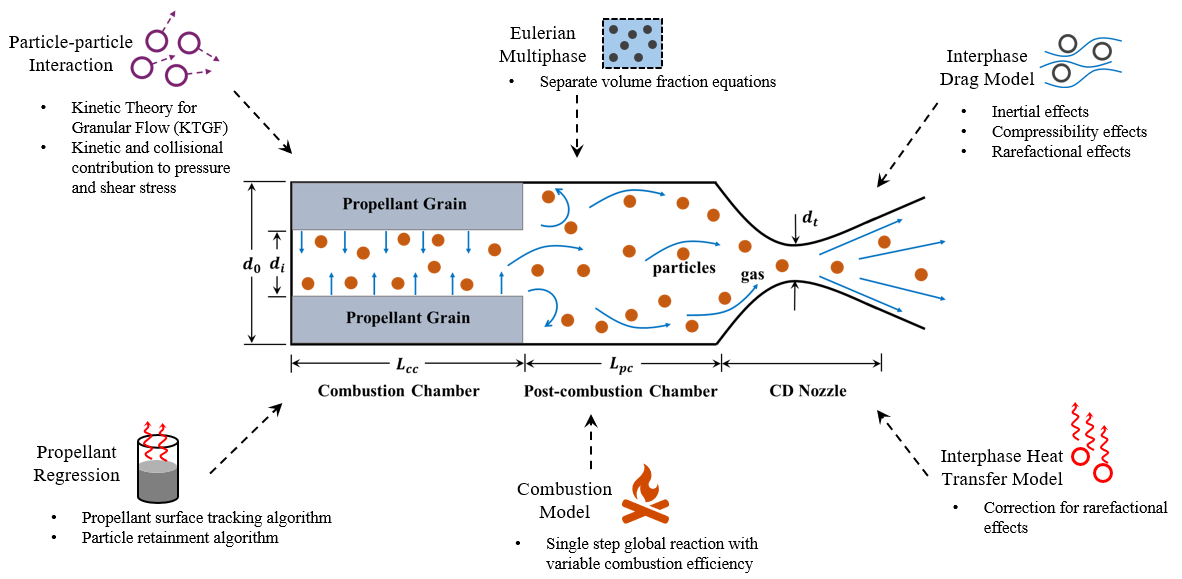
Note: The source terms due to propellant regression are only relevant to the computational cells adjacent to the surface of the propellant bed. For the remaining computational cells inside the rocket motor, only the source terms arising from particle–gas interactions are relevant.
Closure Models
Propellant Surface Regression Model
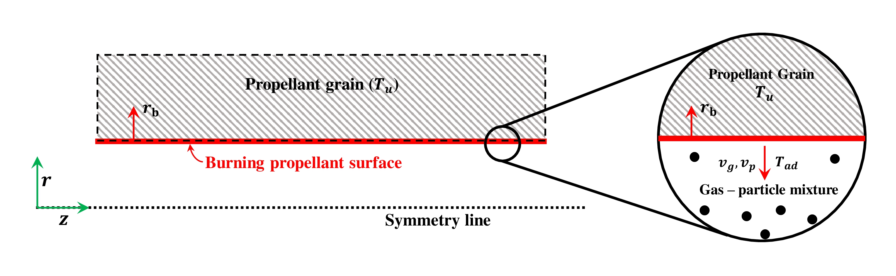
The propellant phase is stationary ($u_{prop}$ = 0). Therefore, only mass and energy conservation equations are solved for the propellant phase. The mass conservation equation for the propellant phase is written as: $$ \frac{d}{dt}(\alpha_{prop} \rho_{prop}) = -\dot{m}'''_{prop} $$ The propellant mass burning rate or propellant mass consumption rate is denoted as $\dot{m}'''_{prop}$, and is a function of propellant burning rate and the burning surface area. The burning rate of the propellant is expressed as the function of pressure as per St. Robert's law. The mass burning rate and the burning rate law is expressed as: $$ \dot{m}'''_{prop} = \rho_{prop}r_bs_b $$ $$ r_b[\text{cm/s}] = a(P[\text{MPa}])^n $$ where, $r_b$ is the burning rate of the propellant with the units of cm/s and $s_b$ is the burning surface area per unit volume of the propellant. The burning rate pressure exponent is denoted as $n$ and the pre-exponential factor is denoted as $a$. The pressure is substituted in the units of MPa in the burning rate expression. The pre-exponential factor and the burning rate pressure exponent are one of the inputs to the program. The available surface regression model can be found here. The energy conservation equation for the propellant phase is written as: $$ \frac{d}{dt}(\alpha_{prop} \rho_{prop} h_{prop}) = -\dot{m}'''_{prop}h_{prop} + \alpha_{prop}\frac{dP}{dt} $$ where, $h_{prop}$ is the enthalpy of the propellant phase. Expressing the energy equation in non-conservative form of the equation in terms of internal energy will lead to $\frac{de_{prop}}{dt} = 0$, suggesting the specific internal energy of the propellant phase is constant. The present framework model does not explicitly resolve the reaction zone. The propellant at the initial temperature is assumed to get converted to products at the interface and the rate of the reaction is dictated by the burning rate law which is one of the input to the model. Therefore, the energy equation for the propellant phase need not be solved.
Combustion Model
The combustion of the propellant is modelled as a single step global reaction: $$ \text{Propellant} \rightarrow \text{Gas phase} + \text{Particle phase} $$ The mass fraction of the gas phase and particle phase can be obtained from the global reaction, and is denoted as $X_g$ and $X_p$, respectively. The mass source term for the particle and gas phase are computed as, $$ \dot{m}'''_{prop\rightarrow g} = X_g\dot{m}'''_{prop} \hspace{30pt} \dot{m}'''_{prop\rightarrow p} = X_p\dot{m}'''_{prop} $$ The momentum source terms for the gas and particle phases are calculated by performing interfacial mass conservation locally near the propellant surface. The interfacial mass balance equation at the propellant surface becomes, $$ \left[\alpha_g \rho_g (\boldsymbol{v}_g \cdot \boldsymbol{\hat{n}} - r_b) \right]s_b + \left[\alpha_p \rho_p (\boldsymbol{v}_p \cdot \boldsymbol{\hat{n}} - r_b) \right]s_b = -\rho_{prop}r_bs_b $$ where the radially outward unit normal vector of the propellant surface is denoted as $\boldsymbol{\hat{n}}$. Assuming the particles are not yet dragged by the gas at the propellant surface, the velocity of the particle phase is taken to be zero ($\boldsymbol{v}_p = 0$). The above equation is used to obtain the velocity of gas phase at the propellant surface. Therefore, the momentum sources of the gas and particle phase due to propellant regression are: $$ \boldsymbol{M}_{prop \rightarrow g} = \dot{m}'''_{prop \rightarrow g}\boldsymbol{v}_g \hspace{30pt} \boldsymbol{M}_{prop \rightarrow p} = \dot{m}'''_{prop \rightarrow p}\boldsymbol{v}_p $$ Note that the interfacial momentum balance should also be considered to obtain the velocity of the gas and particle phase at the propellant surface. Such a balance would suggest that there is a pressure jump across the propellant surface as a result of the thrust force experienced by the propellant phase due to mass ejection. A simple calculation suggests that the thrust force per unit area is of order $\sim$ 1 kPa, and the chamber pressures are much higher than 100 kPa. Therefore, this effect is neglected. The temperature $(T_{ad})$ of the gas and particles entering the combustion chamber is obtained by performing energy balance between reactants and products, i.e., equating the enthalpy of reactants and products. The enthalpy of the gas and particle phase are then computed as: $$ h_{prop \rightarrow k} = \Delta h_{f, k}^0 + \int_{T_{ref}}^{T_{ad}} C_{p, k}(T) \,dT $$ where, $\Delta h_{f, k}^0$ is the enthalpy of formation of $k^{\text{th}}$ phase and $C_{p, k}$ is the constant pressure specific heat of $k^{\text{th}}$ phase. If the gas phase constitutes of mixture of various species, the enthalpy of formation and the constant pressure specific heat can be obtained as weighting based on the mass fractions of the individual species in the mixture. The mass fraction weighted coefficients can be given as inputs to the model. Thus, the enthalpy source term of the gas and particle phase is expressed as, $$ H_{prop \rightarrow g} = \dot{m}'''_{prop \rightarrow g} \hspace{30pt} H_{prop \rightarrow p} = \dot{m}'''_{prop \rightarrow p} $$
Drag Models
Various drag models are included in the library that provides a closure model for the drag coefficient between gas and particle phase. The drag force is calculated from the drag coefficient as follows: $$ \boldsymbol{f}_{D, g} = -\boldsymbol{f}_{D, p} = \frac{3}{4}\frac{\alpha_p\mu_g}{d_p^2}C_D\text{Re}_p(\boldsymbol{u}_p - \boldsymbol{u}_g) $$ where, $d_p$ is particle size, $\mu_g$ is the gas phase viscosity, $C_D$ is the drag coefficient and, $Re_p$ is the particle Reynolds number and is computed as: $$ \text{Re}_p = \frac{\rho_g |\boldsymbol{u}_g - \boldsymbol{u}_p| d_p}{\mu_g} $$ For CD nozzle flows, the gas particle interactions are expected to include compressibility and rarefactional effects in addition to inertial effects. The drag model that includes all these effects is developed by Eric Loth et. al (2021) . For detailed information about the available heat transfer models and their implementation, refer to Particle Drag Models.
Heat Transfer Models
The interphase heat transfer between gas and particle phases are modelled based on Ranz-Marshall correlation. To include rarefactional effects, the correction proposed by Kavanau is used. The heat transfer between gas and particle phases is calculated as follows, $$ Q_{HT, p} = -Q_{HT, g} = 6\frac{\alpha_p\lambda_g}{d_p^2}\text{Nu}(T_g - T_p) $$ where, $\text{Nu}$ is the Nusselt number calculated based on the heat transfer model. For detailed information about the available heat transfer models and their implementation, refer to Heat Transfer Models.
Particle-particle Interaction Models
The particle-particle interactions are modelled based on Kinetic Theory for Granular Flow (KTGF). The solid pressure and solid shear stress is modelled based on the closure models which is a function of granular kinetic energy. A separate governing equation is solved for granular kinetic energy ($\Theta$) and is expressed as: $$ \frac{3}{2} \left[\frac{\partial}{\partial t}(\alpha_p\rho_p\Theta) + \boldsymbol{\nabla}\cdot(\alpha_p\rho_p\Theta \boldsymbol{u}_p)\right] = \left[(-P_p\mathbf{I} + \boldsymbol{\tau}_p):\boldsymbol{\nabla} \boldsymbol{u}_p\right] + \boldsymbol{\nabla}\cdot(\kappa_p\boldsymbol{\nabla}\Theta) - \gamma_p - J_p $$ The first term in the right-hand side of the equation denotes the production of fluctuating energy for the particle phase through stress; the second term is the diffusion of the granular energy; the third term is the dissipation of the fluctuating energy due to inelastic collisions between particles and the fourth term is the production or destruction of energy due to drag force fluctuations exerted on the particle. The following are the available KTGF models that are mirrored from OpenFOAM-v2112.
| Category | Available Models | Key References |
|---|---|---|
| Granular Pressure | Lun's Model, Syamlal-Rogers-O'Brien |
• Lun et al. (1984) • Syamlal et al. (1993) |
| Viscosity & Conductivity | Hrenya-Sinclair, Gidaspow, Syamlal |
• Hrenya & Sinclair (1997) • Gidaspow (1994) • Syamlal et al. (1993) |
| Radial Distribution | Gidaspow, Lun-Savage, Sinclair-Jackson, Carnahan-Starling |
• Gidaspow (1994) • Lun & Savage (1986) • Sinclair & Jackson (1989) • Carnahan & Starling (1969) |
Solution Algorithm
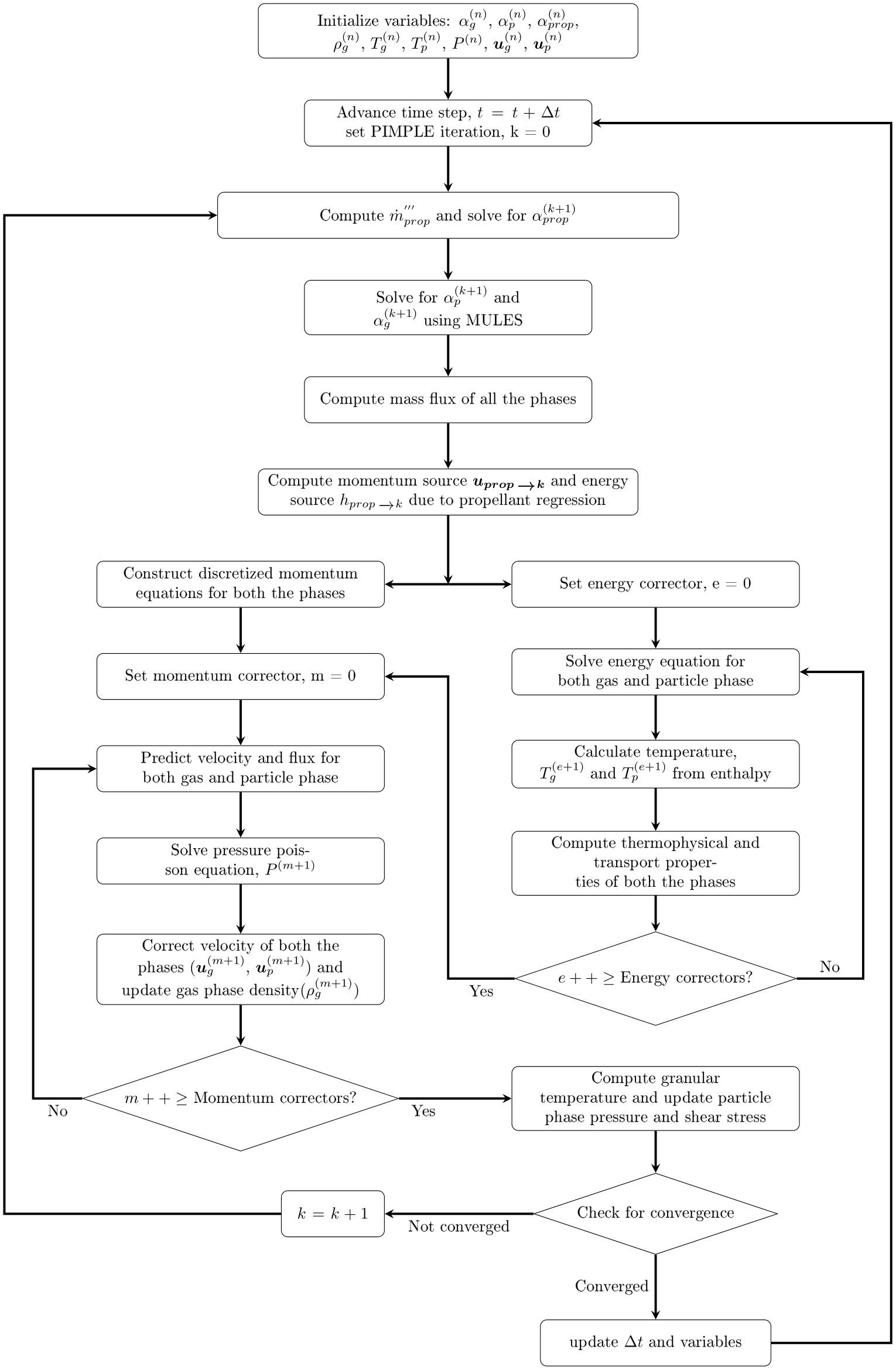
Numerical Methods
The governing equations are discretized using the Finite Volume Method (FVM) framework inherent to OpenFOAM. Consequently, the solver maintains full compatibility with the extensive library of numerical schemes for spatial and temporal derivatives implemented within the OpenFOAM environment. Users may utilize the run-time selection mechanism to specify these schemes via the fvSchemes dictionary, without recompiling the source code.